Monday, November 22, 2010

Schematic differensiator OP-amp

OP-amp differensiator is conducting a series of differentiation in a mathematical operation. The set produces output voltage proportional to the slope of the input voltage. The use of a common set of differensiator is to detect edge ahead and behind the edge of a square pulse or to generate output from input signal square triangle

In the picture above shows a circuit using an op-amp differensiator. The set is almost similar differensiator The set of integrators only resistors and capacitors positions are different. When the input voltage change means that the capacitor currents will remain. Because of all these constant currents flowing through the feedback resistance, then signal at the output of the box, as shown in the picture above

schematic differensiator OP-amp From the equation Vout can be seen that the output voltage is a differensiator deviatif of input voltage versus time multiplied by the time constant differensiator (RCX).
Voltage output (V out) in differensiator OP-amp schematic. Click Here!

Sunday, May 9, 2010

Schematic Power Supply

Schematic Power SupplyThe power supply usually used for experimental work, the power there could be rules ranging from 2 volts to 24 volts with two choices of 60 milliampere currents up to 600 milliampere, then for the stability of the voltage used 3085 CA components, and all the transistors have to wear cooler. Click Here!

Diagram Inverter 12 V dc to 100 V ac

Diagram Inverter 12 V dc to 100 V acDiagram Inverter 12 V dc to 100 V ac. Click Here!

Thursday, May 6, 2010

Tuesday, May 4, 2010

Diagram voltage testers

Diagram voltage testersThis tool voltage tester, can be made easily and components sold in stores, it works to regulate the working potential was also set with the input impedance voltage 3W works, it works with a 9-volt DC power source. Click Here!

Monday, May 3, 2010

Diagram SCR Tester

Diagram SCR TesterSCR circuit testers, look at the composition of only a few components, other components of a seed light.Click Here!


(SCR signs, with the circle, is a tested SCR)

Schematic Alarm Beam Light

Schematic Alarm Beam LightLight beam alarm or anti theft alarm. Click Here!

Saturday, May 1, 2010

Schematic voltage doubler 6V to 12V

This chart is a way to increase the current 12-volt batteries are just so much more than the original size, or 6-volt batteries 12 volt can be done using the street wearing schematic voltage Doubler, by this means we increase the flow of the 6 volt batteries to be 12 volts, while for output details will be doubled from the original input. When the input is only 12 volts so with the help of this tool could be 24 volts, but its exceptions . Small that it is not always input using this tool could be two-fold from its origin. The main cause could be so because the burden is too heavy and it decreased to 10% to 15%, a clear course. The circuit is only for maximum loads up to 200mA.
The circuit is working normally, if the batteries that will be raised that we put the voltage at the point (A) and point (B), and the results are taken at the point (C) and (D) its schematic view, (C) negative and the point (D) positive. While the function of each existing transisitor was of the kind PNP switching transistor type No. 2N404 and transistors to the second type of ASH-26, then 2SA155 or type / other similar type. Type III AC 128 transistors, and transistors to the IV and V respectively AC 127 and AC 128, for details see component data below,
- Resistors (R1) = 1.2 Ohm 1 / 2 Watt
- Resistor (R2) = 22 Ohm 1 / 2 Watt
- Resistors (R3) = 22 Ohm 1 / 2 Watt
- Resistor (R4) = 470 Ohm 1 / 2 Watt
- Resistor (R5) = 270 Ohm 1 / 2 Watt
- Capacitor (C1 = C2 = 0.022 F/400 Volt (Polyester)
- Capacitor (C3 = C4 = 250F/15 Volt (elco)

Transistors and diodes, respectively see this picture:
voltage doubler 6v to 12 V
A second transistor and PNP transistor type 2N404, ASH-26, 2SA155, duties etc. here multivibrator, the transistor 3 and the converter works as a buffer of low and high impendasi outside the transistors 4 and 5, here transistors 5 and 4 served as the complementary outputs systemntry stage. 3 AC 128 Transistor type transistor his fourth and fifth type AC 127, and diodes to and diodes into a well elco (C3) and (C4) type that is used up your free, original condition can be complied with PIV 100 volts with 500 mA current. Click Here!

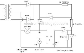
Automatic battery charger

Automatic battery chargerAutomatic battery charger or ABC's highly automated way it works, the battery has discharged its contents, this tool can be used to fill itself automatically and filling in accordance with existing flows, so that damage to the battery cells can be avoided as early as possible, the use of SCR function as SWITCH . Other components are: AC power transformers have figures on the right side as in the scheme below. Click Here!

Tuesday, April 27, 2010

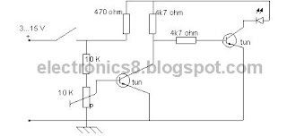
Battery Indicator

Battery indicator is a tool is not serving as a flow battery charger that has been discharged, but rather served as a giver of knowledge that the current battery is running out!. So clearly similar to a mini electric alarm. Power capacity can work at voltages ranging from value of 3 volts DC to 15 volts DC. For the schematic and the material used was very few and easy to be paired on the radio or the lights flash for photos, consider the schematic below clearly;

Battery IndicatorThis appliance is once again not to use the current battery charge longer, so the same name but its function is not the same as the battery indicator is called battery charger! Click Here!

electrical appliance or electronic equipment

If we are dealing with an electrical appliance or a plane, then we often wondered whether the equipment or the aircraft is an electrical appliance or electronic equipment?
To distinguish between those mentioned above earlier, commonly used electrical terms if he is used to run electric motors, generators can make work, lit a lamp, generates heat, making the electric bell rang and made an electric magnet works, and others. But the term is usually used when a elektonika electricity used for the purposes of: aircraft radio transmitter, radio receiver, transmitting television, television receiver, digital clock, digital volt meter, digital phone, osciloscope, radar, frequency counters, vacuum tube volt meter , video tapes, walky talky, radio citizan band, computer, calculator, tranceiver, teleprinter and other tools that use electron tubes, using transistors, using semiconductor diodes, using IC (Integrated Circuit).
It is an electric power energy such as light, heat, chemical and energy of motion. As for the names of the electrical energy can be converted into light energy is electric light, electrical energy can be converted into heat energy is electric irons, electric energy is converted into chemical energy and electrical energy accumulator that can be converted into energy of motion is a magnet and another another. Click Here!

Monday, April 26, 2010

Rectification

RectificationThe essntial item in the Rectification process is the diode.
The word 'diode' is made up from di (=two) + electrode, and it is therefore a device which has two electrodes or terminals. These terminals are called anode and cathode respectively. Identification of the cathode is by means of marking the appropriate end the body of the component, usually with a band.
The diode is a one-way device, that is, it will conduct, or allow current to flow, in one direction only, when its anode is positive with respect to cathode. The direction in which this current flows is called the forward direction.
When the anode is negative with respect to the cathode, no current should flow.
This is called the reverse direction.
The diode can regarded as a switch, current able to flow only when the switch is on. Click Here!

DC power supply

Although the use of thermionic valves may be making a comeback in some quarters, the great attraction of transistors and integrated circuits in, for example, personal stereos and other low-output power equipment, is the 'carry everywhere' aspect, which is in no small measure due to the low-voltage, low-power supply that the equipment requires.
As most users will know, this power supply can easily be provided by batteries, with the cost aspect connsidered by the use of rechargeable batteries. The wisdom of using a mains adaptor to reduce running costs to a minimum is advocated, although of course, portability is reduced.
For higher output powers, as offered by domestic high fidelity equipment, the use of batteries is not an economic proposition.

A DC (direct current ) power supply is an item of equipment which provides a unidirectional (in one direction only) voltge which ideally should be constant.

DC power supply necessary is electronic equipment requiers an operating supply voltge which is of type described above. this voltage could range in value from a few hundred volts in the days of thermionic valves, to between three and, say 50 volts for modern-day with batteries.

The function of DC power supply is to provvide a constant ( or near constant) voltage while delivering a possible wide range of currents to the equipment. The actual current demand can sometimes depend uponthe operating state of equipment-for example, with an audio amplifier, the actual volume level.
It can be mentioned here that there are cetain applications which require a constant current supply as opposed to constant voltage.

This DC power supply achieved is from the AC (alternating current) mains, through a conversion process known as rectification

The AC input voltage is shown as alternating above and below zero, that is, going alternately positive and negative, at a rate ( frequency) of 50 times a second (50 hertz).
The DC output voltage is shown as a positive value, but it could, if necessary, be negative

DC power supply The AC input voltage is shown as alternating above and below zero, that is, going alternately positive and negative, at a rate ( frequency) of 50 times a second (50 hertz).
The DC output voltage is shown as a positive value, but it could, if necessary, be negative. Click Here!